
No products
Product successfully added to your shopping cart
There are 0 items in your cart. There is 1 item in your cart.
Immunity and Emissions Testing
- EMC Test Equipment
- Transient Generators
- RF Power Amplifiers
- DC - 300 kHz RF Amplifiers
- 10 kHz - 250 MHz RF Amplifiers
- 10 kHz - 400 MHz RF Amplifiers
- 10 kHz - 1 GHz RF Amplifiers
- 80 MHz - 1 GHz RF Amplifiers
- 1 GHz - 2 GHz RF Amplifiers
- 700 MHz - 4.2 GHz RF Amplifiers
- 1 GHz - 6 GHz RF Amplifiers
- 2 GHz - 8 GHz RF Amplifiers
- 6 GHz - 18 GHz RF Amplifiers
- 18 GHz - 40 GHz RF Amplifiers
- Pulse Amplifiers
- RF Field Strength Probes & Meters
- RF Conducted Immunity
- EMC Receivers/EMI Analyzers
- EMC Antennas
- Coupling Decoupling Networks (CDN's)
- Line Impedance Stabilization Networks (LISN's)
- RF Test Equipment
- EMC Probes
- EMC Measurement & Equipment Software
- Power Supplies
- Electrical Safety Analyzers
- High Precision Laboratory Power Analyzers & Meters
- Anechoic Chambers
- Over-the-Air (OTA) Test Chambers
- EMI RF Shielded Tent Enclosures
- RF Shielded Rooms
- EMC Absorber
- Positioning Equipment
- EMC/EMI Test Setup
- GTEM Cells / TEM Cells
- Reverberation Chambers
- Used RF Anechoic Chambers
- EMC Chamber Filters
- EMC Chamber Shielding Gaskets
- RF Shielded Doors
- Anechoic Chamber Accessories
- Fully Anechoic (FAR) Test Chambers
- Manufacturers
- 3ctest
- AE Techron
- AH Systems
- Amplifier Research
- Boonton
- Com-Power
- Diamond Engineering
- EM Test (Ametek CTS)
- EMC Partner
- EMC Test Design
- Empower High Power RF Amplifiers
- ETS-lindgren
- Log Periodic Dipole Array Antenna
- Near Field Probe Sets
- Double Ridge Horn Antennas
- Biconical Antennas
- Quad Ridge Horn Antennas
- Electric Field Probes
- GTEM's
- Positioners & Tripods
- Loop Antennas
- Biconilog Antennas
- LISN's (Line Impedance Stabilization Network)
- Shielded Enclosures/Rooms
- Monopole Antennas
- Field Generating Antennas
- Fischer Custom Communications
- Haefely Hipotronics
- Haefely EFT/Burst Immunity Test Systems
- Haefely Surge Combination Wave Test Systems
- Haefely Surge Damped Oscillating Wave Test Systems
- Haefely Electrostatic Discharge Test Systems (ESD)
- Haefely Surge Ring Wave Test Systems
- Haefely Surge Telecom Wave Test Systems
- Haefely Magnetic Field Test Systems
- Haefely CDN's (Coupling/Decoupling Networks)
- IFI Amplifiers
- Keysight (Agilent)
- MVG - Microwave Vision Group
- PMM / Narda
- Rohde & Schwarz RF Test Equipment
- Rohde & Schwarz Broadband RF Amplifiers
- Rohde & Schwarz Spectrum Analyzers
- Rohde & Schwarz Compliant EMI Test Receivers
- Rohde & Schwarz Isotropic RF Probes
- Rohde & Schwarz RF Signal Generators
- Rohde & Schwarz RF Switches
- Rohde & Schwarz Oscilloscopes
- Rohde & Schwarz RF Power Meters
- Rohde & Schwarz RF Power Sensors
- Schloder
- Schwarzbeck Mess-Elektronik
- Schwarzbeck Antennas
- Schwarzbeck Automotive Antennas
- Schwarzbeck Broadband Horn Antennas
- Schwarzbeck Biconical Antennas
- Schwarzbeck Logarithmic Periodic Broadband Antennas
- Schwarzbeck Stacked Log-Periodic Broadband Antennas
- Schwarzbeck Biconic Log-Periodic Antennas
- Schwarzbeck Dipole Antennas
- Schwarzbeck Rod Antennas
- Schwarbeck Antenna Baluns / Holders
- Schwarzbeck LISN Line Impedance Stabilisation Networks
- Schwarbeck Decoupling & Absorbing Clamps
- Schwarzbeck Field Probes
- Schwarzbeck Helmholtz Coils
- Schwarzbeck Antenna Masts
- Schwarzbeck Coupling/Decoupling Networks
- Schwarzbeck Antennas
- Solar Electronics
- Teseq (Schaffner)
- Teseq Automotive Transient Generators
- Teseq RF Test Equipment
- Teseq EFT/Burst Generators
- Teseq RF Immunity Generators
- Teseq ESD Guns
- Teseq Surge Generators
- Teseq Harmonics & Flicker Solutions
- Teseq Dips, Interrupts & Variations Equipment
- Teseq Ring Wave Generators
- Teseq Oscillatory Waves Generators
- Teseq Absorbing Clamps / Ferrite Tube
- Teseq EMC Antennas
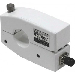
- Teseq Current Probes
- Teseq Coupling Networks
- Thermo Keytek
- Vicreate
- Compliance Standards
- International (IEC/EN)
- EN/IEC 61000-3-2
- EN/IEC 61000-3-3
- IEC 61000-3-11
- IEC / EN 610000-3-12
- EN/IEC 61000-4-2
- EN/IEC 61000-4-3
- EN/IEC 61000-4-4
- EN/IEC 61000-4-5
- EN/IEC 61000-4-6
- EN/IEC 61000-4-7
- EN/IEC 61000-4-8
- EN/IEC 61000-4-9
- EN/IEC 61000-4-10
- EN/IEC 61000-4-11
- EN/IEC 61000-4-12
- EN/IEC 61000-4-16
- EN/IEC 61000-4-18
- EN/IEC 61000-4-19
- EN/IEC 61000-4-20
- EN/IEC 61000-4-21
- EN/IEC 61000-4-29
- EN/IEC 61000-4-31
- IEC 61000-4-39
- EN/IEC 62132
- SEMI F47 Voltage Sag Immunity
- Product Standards
- Military & Aerospace Standards
- Automotive EMC Standards
- CISPR Standards
- Telecom Testing
- ANSI/IEEE Standards
- FCC Part 15
- FCC Part 30
- International (IEC/EN)
- Application/Test Type
- Radiated Immunity
- Bulk Current Injection Testing
- RF Emissions Testing
- Conducted Immunity
- Conducted Emissions
- Antenna Pattern Measurement
- CE Mark Testing
- Intentional Radiator Testing
- Pulsed HIRF Radar
- Over-the-Air (OTA) Testing
- 5G Test Solutions
- Automotive EMC
- SAR Measurement Equipment
- Radiated Emissions
- Battery Simulator Test Equipment
- Services
- Clearance
Viewed products
-

Em Test CWS 500N1.4 RF...
Test procedure acc. IEC 61000-4-6 Ed....
 View larger
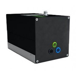
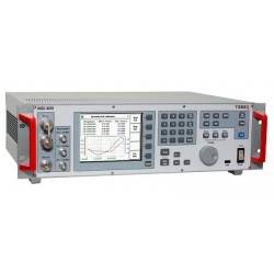
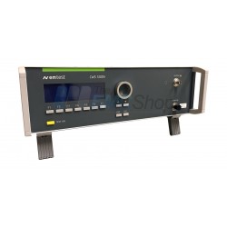
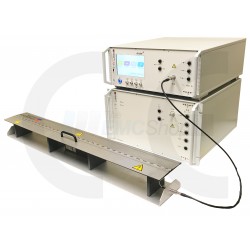
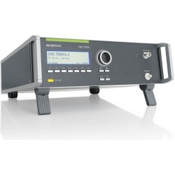
Em Test CWS 500N1.4 RF Conducted Immunity Test System for IEC 61000-4-6
Refurbished
- Test procedure acc. IEC 61000-4-6 Ed. 4
- Built-in amplifier saturation and linearity check
- Built-in power amplifier 25 to 80 watts, 10 kHz to 400 MHz
- Built-in power meter, 9 kHz to 1 GHz
- Built-in dual directional coupler
- Automatic calibration via built-in power meter
- Connection for external amplifiers up to 1 GHz
- USB-Interface
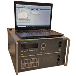
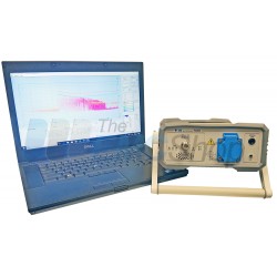
- Software for Windows 7, Windows 8
Typically In Stock
PDF Downloads
Test Equipment Description
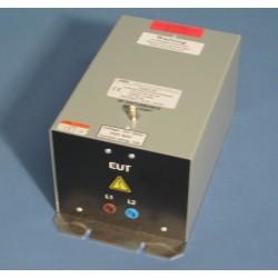
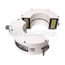
The CWS 500N1.4 is the most compact single box test equipment for testing conducted rf immunity per IEC 61000-4-6 Ed. 3 and Ed. 4 and related standards with a frequency range of 100 kHz to 300 MHz. Apart from the 1 kHz 80 % AM signal the generator also generates a 2 Hz 80 % AM signal to test medical appliances and a 1 Hz PM signal with 50 % duty cycle required to test safety equipment like fire alarms. Equipped with a 1 GHz current monitor the CWS 500N1.4 can be used up to 1 GHz by means of an external amplifier. EM TEST supplies a large range of CDNs, EM clamp and current injection clamps as well as the corresponding calibration accessories. Full compliant levelling can be run from the front panel of the CWS 500N1.4 storing the results in 5 memory spaces is available.
Operating Functions
Front Panel | |
 | |
| 1 | "Test On" By pressing the key "TEST ON", the test procedure can be started with the pre-selected parameters and amplifier is turned ON. | 7 | Escape The ESC button returns back to the previous level in the menu. |
| 2 | Function Keys "F1 .. F7" Parameters and functions displayed in the lowest line and functions displayed with ”F “, can be selected with the related function key. | 8 | LED Current Probe Input At the BNC output the current pulse of the generator can be measured. Dividing ratio is 10:1 (5V at 50A pulse). |
| 3 | Display All functions and parameters are displayed (8 lines with max. 40 characters). | 9 | LED RF Output When the RF output is active this LED on the front panel is illuminated to indicate that a test signal is applied to the test object. |
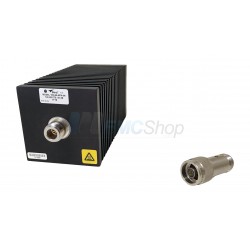
| 4 | EXIT The EXIT button resets the firmware to the main menu. This is only possible, if no test routine is running. | 10 | RF-Output At this output the RF power is available. The 6dB-attenuator is connected via coaxial cable. For conducting tests together with CDN’s, EM clamps or current injection clamps, the generator must always be loaded with a 6dB-attenuator as per IEC 61000-4-6. |
| 5 | Cursor key Parameters and functions can be changed during the test. The selection of these parameters is done with the cursor, moving it to the left or to the right. The increment value of the selected parameters in the lowest line can also be selected with the cursor key. | 11 | Current Probe Input For tests with a coupling clamp where the EUT current has to be monitored, the current probe can be connected to this input. |
| 6 | Exit Knob (Inc / Dec) This knob increments or decrements test parameters with a numeric value or selects parameters from a list. | ATTENTION: Do not connect the RF output directly to this input otherwise the CWS500 might damage. | |
Rear view | |
 | |
| 1 | Bridge AMP OUT – Coupler IN | 7 | IEEE Interface |
| 2 | Air output | 8 | USB Serial Interface |
| 3 | Bridge SG OUT – AMP IN | 9 | Remote Control Connector Not used. |
| 4 | Safety Circuit | 10 | Fail 1 Detection "Stop" The BNC input FAIL 1 is for failure detection on the EUT. If the input is set to ground (chassis), the CWS 500N1.x generator stops the actual test routine and terminates the test. It is not possible to continue the test routine. A complete restart of the routine will be necessary. The message "FAIL 1" indicated on the LCD-Display as well as in the icd.control software. |
| 5 | Power On Switch and Fuse | 11 | Fail 2 Detection "Pause" The BNC input FAIL 2 is for failure detection on the EUT. If the input is set to ground (chassis), a failure event detects, and the test continues normally. After 10 FAIL 2 events the program will stop and the message "FAIL 2: 10" indicates on the LCD-Display as well as in the icd.control software. |
| 6 | Power selector 115V – 230V |
| Technical Data | ||
| Test Level CWS 500N1.3 | ||
| Output Level | 1 - 30Ve.m.f. after 6dB-attenuator | |
| Output power | 80W (nominal) | |
| Output impedance | 50 Ohm | |
| max. VSWR | 1:1.2 at all phase angles and at max. power (without destruction) | |
| Harmonic distortion (at max. power) | < 15dBc | |
| Test frequencies | CWS 500N1.3 | CWS 500N1.4 |
| Sinusoidal (CW) | 10 kHz – 400 MHz | 100 kHz – 300 MHz step: 1kHz |
| In the menu QUICK START the step size can be selected by the user | ||
| Modulation | ||
| Modulation method | Amplitude modulation 80% <±5% and 1kHz <±10% acc. to IEC 61000-4-6 80% <±5% and 2Hz, 1kHz acc. to IEC 60601-1-2 | |
| Pulse modulation | 1Hz, 50% duty cycle acc. to EN 50130-4 | |
| General | 80% at Frequencies 2Hz, 400Hz,1kHz | |
| Other modulation | via ICD software Settings in Vector mode | |
| Signal Generator | ||
| Output level | -63.5 dBm to 0 dBm | |
| Step level | 0.5 dB | |
| Frequency range | 9 kHz to 1 GHz | |
| Output impedance | 50 ohm | |
| Calibration measurements | ||
| Cal data | 5 internal stores for calibration data. | |
| ICD | Software for the upload and download of Cal-files. | |
| LCD | On-line display of the test level and the preselected frequencies. | |
| Monitor input PM1000 | RF monitor input for calibration procedures and current probes measurement. Input voltage for current monitoring V max = 1.0 V rms (13dBm) | |
| Cal data for current probe (CP) | 2 internal stores ; ( download with ICD software ) A download will reduce data to 10/ decade and frequency range 100kHz ... 300MHz | |
| Timing | ||
| Dwell time | general td = 0,3s - 9999.9s pulse modulation td = 3s - 9999.9s | |
| Rest time | tr = 0 / 0,3s - 9999.9s | |
| Output | ||
| Direct | N | |
| EUT control | ||
| BNC input | FAIL 1 Fail 1; test will be stopped immediately | |
| BNC input | FAIL 2 Fail 2; failure is detected, test continues (max. 10 failures) | |
| Test routines (integrated) | ||
| Quick Start | Immediate start, all parameters adjustable during testing. | |
| User test routines | 1. Voltage sweep 2. Frequency sweep 3. Dwell time sweep | |
| Standard test routines. | 1. Level 1-3 acc. to IEC 61000-4-6 2. Automatic Level X - Level Y | |
| Cal procedure | Calibration of the complete test set-up. Internal storage of the Cal-files. | |
| Service | Service, Setup | |
| Interfaces | ||
| Serial Interface | USB | |
| Parallel IEEE 488 GPIB interface | Addresses 1 - 30 selectable All interfaces are included as standard features. | |
| Power meter PM 1000 | ||
| Frequency range | 9kHz – 1000 MHz | |
| Input range | Monitor -45 dBm ... +13 dBm FWD power -50 dBm ... +13 dBm REV power -50 dBm ... +13 dBm | |
| Max. Input MONITOR | 13dBm approx. 1.0 Vrms | |
| Accuracy | < ± 0.5 dB ( 0.09MHz...400MHz ) < ± 1.0 dB ( 0.01MHz...1000MHz ) | |
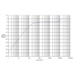
| Dual Directional Coupler | ||
| Frequency range | 10kHz – 1000 MHz | |
| Power | 150 W max. | |
| Insertion loss | 0.6 dB max. | |
| Mainline VSWR | 1.1:1 max. | |
| RF Amplifier ( build in ) | CWS 500N1.3 | CWS 500N1.4 |
| Class of Operation | Class A | Class A |
| Frequency range | 10 kHz .. 400 MHz | 100 kHz .. 300 MHz |
| Output power nominal | 80 W | 80 W |
| Gain | 48 dB nominal | 48 dB nominal |
| Input power for rated output | 0 dBm | 0 dBm |
| Input power max. | 10 dBm | 10 dBm |
| Input / Output Impedance | 50 Ω | 50 Ω |
| Input VSWR | 1.5: 1 max. | 1.5: 1 max. |
| General Data | ||
| Dimensions | 19"/3HE | 19"/3HE |
| Weight | 17.25 kg | 14.95 kg |
| Power supply | 110-230V/ max 50/60Hz | |
| Input power | max. 380W | |
| Power factor | cosΦ=0,98 at max output power | acc. to IEC 555 |
| Fuse | 230V: 2x3,15AT 115V: 2x6.3AT | |
| Cooling | Active cooling, air ventilation | |
| Environment conditions | 10°C - 35°C | 10°C - 40°C |
| Humidity | Max. 85 %, non condensing | |
How to Order the EM Test CWS 500N1.4:
- Click "Add to Cart" above
- Register or Check Out as a Guest
- Select Shipping Method (use "My Account" and input your account # and method)
- Agree to Terms & Conditions
- Payment Method Options: Credit Card or Submit A Purchase Order
- Order Confirmation and Tracking Info Follows
Associated EMC Test Equipment


30 other products in the same category:
-
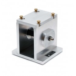
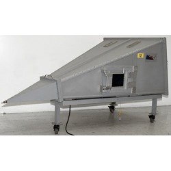
Teseq GTEM 1500 GTEM Cell for Emissions and Immunity Testing
-

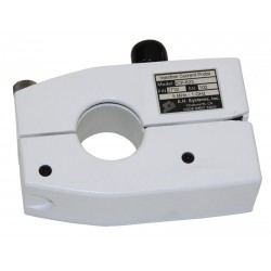
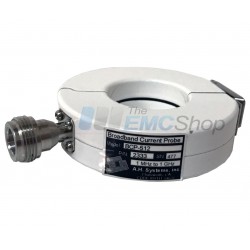
AH Systems ICP-621 Current Injection Probe, 10 kHz - 100 MHz
-

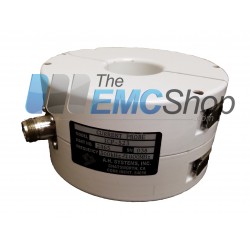
AH Systems ICP-622 RF Current Injection Probe, 1 MHz - 500 MHz
-
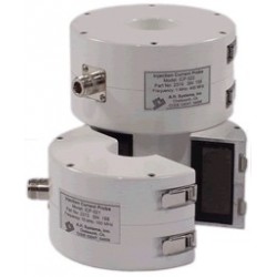
AH Systems ICP-623 RF Current Injection Probe, 5 MHz - 1 GHz
-
Rent AH Systems ICP-523 RF Current Injection Probe, 300 kHz - 1 GHz
-
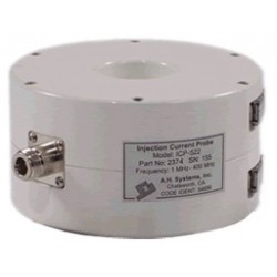
AH Systems ICP-522 RF Current Injection Probe, 1 MHz - 400 MHz
-
AH Systems ICP-521 Current Injection Probe, 10 kHz - 100 MHz
-
Teseq NSG 4070B Conducted & Radiated Immunity Test System
-
Em Test CWS 500N3 Test Generator for Mil-STD-461, ISO 11452 and More
-
AH Systems BCP-512 Probe to Measure Conducted RF Currents, 1 MHz - 1 GHz
-
AH Systems BCP-610 High Power RF Current Probe, 20 Hz - 20 MHz
-
Rent AH Systems BCP-611 10 KHz – 150 MHz Broadband Current Probe
-
Narda PMM 7010 EMI Test Receiver
-
AH Systems BCP-614 Probe to Measure Conducted RF Currents, 10 KHz - 300 MHz
-
EM Test CWS 500N1 Continuous Wave Simulator for IEC 61000-4-6
-
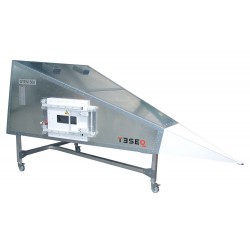
Teseq GTEM 500 GTEM Cell for Emissions and Immunity Testing
-
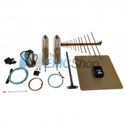
Rent AH Systems EMC Antenna Kit, 20 Hz to 2 GHz
-
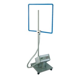
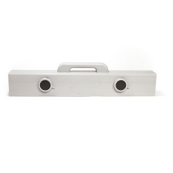
PMM 1008 Magnetic Field Generator with Loop Antenna, 1200 A, 50/60 Hz, IEC/EN 61000-4-8
-

Rent Teseq NSG 4070C-45 Test System for Conducted & Radiated Immunity
-
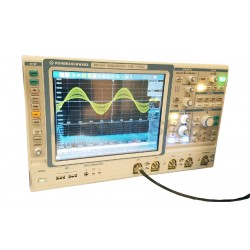
Rohde & Schwarz (R&S) RTE1204 Digital Oscilloscope, 2 GHz, 4 channels, 5 Gsample/s, 10/40 Msample
-
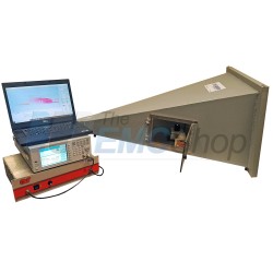
MIL-STD-461 RF Shielded Chamber for Emissions & Susceptibility Testing
-
CE Mark Product Package for IEC/EN 61000-4 Series Compliance
-
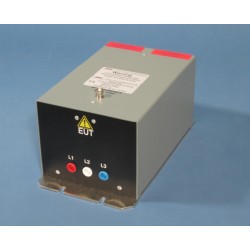
Turn-Key Solution for EFT/Burst, Surge Combination Wave with 3-Phase CDN and EFT Clamp up to 5 kV
-
Teseq NSG 4070C-80 Integrated Signal Generator, 4 kHz to 1 GHz, 80 W Integrated Class A Power Amplifier
-
ETS-Lindgren 5405 RF Emissions and Immunity Test Cell
-
Rent ETS-Lindgren 5402 GTEM Test Cell for Small DUT
-

Monthly Rental EM Test CWS 500N Continuous Wave Simulator for IEC 61000-4-6
-
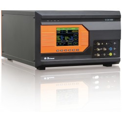
3ctest CCS 500 Compact Immunity Test System
-
EM Test CWS 500N1.3 10 kHz to 400 MHz Continuous Wave Simulator
-
Langer EMV-Technik Z23-2 Set Shielding Tent