
No products
Product successfully added to your shopping cart
There are 0 items in your cart. There is 1 item in your cart.
EMC Test Equipment
- EMC Test Equipment
- Transient Generators
- RF Power Amplifiers
- DC - 300 kHz RF Amplifiers
- 10 kHz - 250 MHz RF Amplifiers
- 10 kHz - 400 MHz RF Amplifiers
- 10 kHz - 1 GHz RF Amplifiers
- 80 MHz - 1 GHz RF Amplifiers
- 1 GHz - 2 GHz RF Amplifiers
- 700 MHz - 4.2 GHz RF Amplifiers
- 1 GHz - 6 GHz RF Amplifiers
- 2 GHz - 8 GHz RF Amplifiers
- 6 GHz - 18 GHz RF Amplifiers
- 18 GHz - 40 GHz RF Amplifiers
- Pulse Amplifiers
- RF Field Strength Probes & Meters
- RF Conducted Immunity
- EMC Receivers/EMI Analyzers
- EMC Antennas
- Coupling Decoupling Networks (CDN's)
- Line Impedance Stabilization Networks (LISN's)
- RF Test Equipment
- EMC Probes
- EMC Measurement & Equipment Software
- Power Supplies
- Electrical Safety Analyzers
- High Precision Laboratory Power Analyzers & Meters
- Anechoic Chambers
- Over-the-Air (OTA) Test Chambers
- EMI RF Shielded Tent Enclosures
- RF Shielded Rooms
- EMC Absorber
- Positioning Equipment
- EMC/EMI Test Setup
- GTEM Cells / TEM Cells
- Reverberation Chambers
- Used RF Anechoic Chambers
- EMC Chamber Filters
- EMC Chamber Shielding Gaskets
- RF Shielded Doors
- Anechoic Chamber Accessories
- Fully Anechoic (FAR) Test Chambers
- Manufacturers
- 3ctest
- AE Techron
- AH Systems
- Amplifier Research
- Boonton
- Com-Power
- Diamond Engineering
- EM Test (Ametek CTS)
- EMC Partner
- EMC Test Design
- Empower High Power RF Amplifiers
- ETS-lindgren
- Log Periodic Dipole Array Antenna
- Near Field Probe Sets
- Double Ridge Horn Antennas
- Biconical Antennas
- Quad Ridge Horn Antennas
- Electric Field Probes
- GTEM's
- Positioners & Tripods
- Loop Antennas
- Biconilog Antennas
- LISN's (Line Impedance Stabilization Network)
- Shielded Enclosures/Rooms
- Monopole Antennas
- Field Generating Antennas
- Fischer Custom Communications
- Haefely Hipotronics
- Haefely EFT/Burst Immunity Test Systems
- Haefely Surge Combination Wave Test Systems
- Haefely Surge Damped Oscillating Wave Test Systems
- Haefely Electrostatic Discharge Test Systems (ESD)
- Haefely Surge Ring Wave Test Systems
- Haefely Surge Telecom Wave Test Systems
- Haefely Magnetic Field Test Systems
- Haefely CDN's (Coupling/Decoupling Networks)
- IFI Amplifiers
- Keysight (Agilent)
- MVG - Microwave Vision Group
- PMM / Narda
- Rohde & Schwarz RF Test Equipment
- Rohde & Schwarz Broadband RF Amplifiers
- Rohde & Schwarz Spectrum Analyzers
- Rohde & Schwarz Compliant EMI Test Receivers
- Rohde & Schwarz Isotropic RF Probes
- Rohde & Schwarz RF Signal Generators
- Rohde & Schwarz RF Switches
- Rohde & Schwarz Oscilloscopes
- Rohde & Schwarz RF Power Meters
- Rohde & Schwarz RF Power Sensors
- Schloder
- Schwarzbeck Mess-Elektronik
- Schwarzbeck Antennas
- Schwarzbeck Automotive Antennas
- Schwarzbeck Broadband Horn Antennas
- Schwarzbeck Biconical Antennas
- Schwarzbeck Logarithmic Periodic Broadband Antennas
- Schwarzbeck Stacked Log-Periodic Broadband Antennas
- Schwarzbeck Biconic Log-Periodic Antennas
- Schwarzbeck Dipole Antennas
- Schwarzbeck Rod Antennas
- Schwarbeck Antenna Baluns / Holders
- Schwarzbeck LISN Line Impedance Stabilisation Networks
- Schwarbeck Decoupling & Absorbing Clamps
- Schwarzbeck Field Probes
- Schwarzbeck Helmholtz Coils
- Schwarzbeck Antenna Masts
- Schwarzbeck Coupling/Decoupling Networks
- Schwarzbeck Antennas
- Solar Electronics
- Teseq (Schaffner)
- Teseq Automotive Transient Generators
- Teseq RF Test Equipment
- Teseq EFT/Burst Generators
- Teseq RF Immunity Generators
- Teseq ESD Guns
- Teseq Surge Generators
- Teseq Harmonics & Flicker Solutions
- Teseq Dips, Interrupts & Variations Equipment
- Teseq Ring Wave Generators
- Teseq Oscillatory Waves Generators
- Teseq Absorbing Clamps / Ferrite Tube
- Teseq EMC Antennas
- Teseq Current Probes
- Teseq Coupling Networks
- Thermo Keytek
- Vicreate
- Compliance Standards
- International (IEC/EN)
- EN/IEC 61000-3-2
- EN/IEC 61000-3-3
- IEC 61000-3-11
- IEC / EN 610000-3-12
- EN/IEC 61000-4-2
- EN/IEC 61000-4-3
- EN/IEC 61000-4-4
- EN/IEC 61000-4-5
- EN/IEC 61000-4-6
- EN/IEC 61000-4-7
- EN/IEC 61000-4-8
- EN/IEC 61000-4-9
- EN/IEC 61000-4-10
- EN/IEC 61000-4-11
- EN/IEC 61000-4-12
- EN/IEC 61000-4-16
- EN/IEC 61000-4-18
- EN/IEC 61000-4-19
- EN/IEC 61000-4-20
- EN/IEC 61000-4-21
- EN/IEC 61000-4-29
- EN/IEC 61000-4-31
- IEC 61000-4-39
- EN/IEC 62132
- SEMI F47 Voltage Sag Immunity
- Product Standards
- Military & Aerospace Standards
- Automotive EMC Standards
- CISPR Standards
- Telecom Testing
- ANSI/IEEE Standards
- FCC Part 15
- FCC Part 30
- International (IEC/EN)
- Application/Test Type
- Radiated Immunity
- Bulk Current Injection Testing
- RF Emissions Testing
- Conducted Immunity
- Conducted Emissions
- Antenna Pattern Measurement
- CE Mark Testing
- Intentional Radiator Testing
- Pulsed HIRF Radar
- Over-the-Air (OTA) Testing
- 5G Test Solutions
- Automotive EMC
- SAR Measurement Equipment
- Radiated Emissions
- Battery Simulator Test Equipment
- Services
- Clearance
Viewed products
-

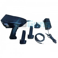
Langer EMV-Technik...
Optical Fibre Probe 1-Channel, 25...


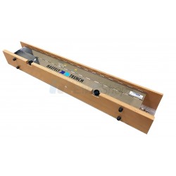
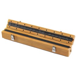
Langer EMV-Technik A100-1 Set 25 kHz Optical Fibre Probe 1-Channel
New
- Optical Fibre Probe 1-Channel, 25 kHz
- Used for oscillating analog signals under EFT/ESD/RF interference
- Suitable for the measurement of analog signals
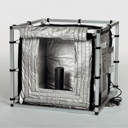
- Suitable for signal control in an anechoic chamber or EMC-compliant space
- It consists of a sensor which measures an analog signal
- Optical signals are transmitted via a fibre optical cable to the optical receiver
PDF Downloads
Test Equipment Description
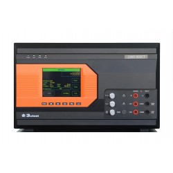
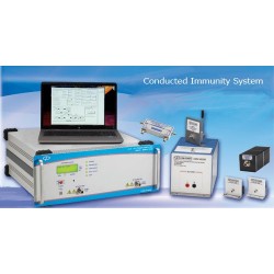
The A100-1 Set is used for oscillating analog signals under EFT/ESD/RF interference. The set is particularly suitable for the measurement of analog signals when testing the immunity of electrical or electronical devices (equipment) against high-frequency electromagnetic fields (IEC 61000-4-3 to IEC 61000-4-6). This system is suitable for signal control in an anechoic chamber or EMC-compliant space. The set consists of a sensor which measures an analog signal within the device under test and transforms it into optical signals. The optical signals are transmitted via a fibre optical cable to the optical receiver which then transforms them into electrical signals. Those can be seen with an oscilloscope or can be used for controlling other devices. For signal detecting within the device under test several sensor types AS100, AS110 or AS120 with different measuring ranges are available.
The signal influence of the prescribed modulation models for electromagnetic fields can be easily detected using the A100 set, A200 set and A300 set analog measuring systems. Hard- and software can be EMC-optimized, because disturbed signals can be easily detected.
Scope of delivery
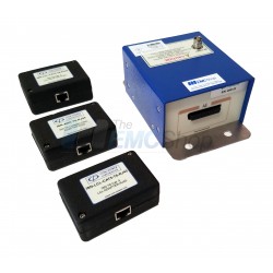
1x AE 100, Optical Receiver
1x AS 100, Optical Sensor (50 / 10) V DC
1x LWL Ø 2.2 mm 1.5 m, Optical Fibre Single 1.5 m
1x NT FRI EU, Power Supply Unit
1x A100-1 acc, Accessories
1x A100-1 case, System Case
1x Analog m, User Manual
| Technical Parameters | |
| Bandwidth | DC ... 25 kHz |
| Sampling rate | 125 kbps |
| Resolution | 12 Bit |
| AE 100 Optical Receiver | |
| Bandwidth | DC ... 25 kHz |
| Optical input: Optical fiber | Ø 2.2 mm |
| Voltage range - output | 0 V ... 10 V |
| Supply voltage | 12 V ... 16 V |
| Current input | ≈ 30 mA |
| Connector - output | BNC |
| AS 100 Optical Sensor | |
| Bandwidth | DC ... 25 kHz |
| Sampling rate | 125 ksps |
| Measuring range | 0 V ... 50 V / 0 V ... 10 V DC (switchable) |
| Input resistance | 100 kΩ |
| Radiated immunity | > 200 V/m |
| Supply voltage | 3 V ... 16 V |
| Current input | ≈ 3 mA |
| Optical fibre length | 1 m ... 20 m |
Usage
Measurement under interference conditions
Measurement of analogue electrical signals under extreme electromagnetic stress such as:
- Coupling of radiated or conducted RF emissions
- Fast transients burst/ESD
- High potential (high voltage)
EMC tests as the main field of application:
- Radiated RF emissions EN 61000-4-3: 80 MHz - 1 GHz, 80% AM (1 kHz), anechoic chambers TEM cells stripline,
- Conducted RF emissions EN 61000-4-6: 40 Veff, 150 kHz - 230 MHz, 80% AM (1 kHz)
- Burst EN 61000-4-4
- ESD EN 61000-4-2
Measured signals:
- Supply voltages (switching controllers, linear controllers),
- Reference voltages,
- Digital signals (optical couplers, optical receivers),
- Analogue signals (operational amplifiers, ADC, DAC).
Specific measurement technology:
To measure analogue signals under extreme interference conditions, measurement technology is needed that
- itself is not affected by disturbance fields and thus does not simulate any disturbance in the equipment under test (EUT).
- can be connected to the EUT in a decoupled way, i.e. connecting the probe head does not result in the development of additional disturbance current paths through which disturbances can penetrate or be discharged.
The A100 / A200 / A300 optical fibre measurement systems meet these demands.
Specific measuring task
Analogue electronic modules are generally influenced in EMC tests when RF, modulated by 1 kHz, is applied to the EUT. This influence is due to the fact that the infiltrated RF disturbance is demodulated at PN junctions of the electronic circuit. This generates signal level fluctuations or 1 kHz disturbance signals. The 1 kHz disturbance signal is produced through modulation of the RF disturbance by 1 kHz.
Relatively slow disturbance signals with a fundamental wave of 1 kHz, which mostly interfere with analogue circuits, are charac-teristic for RF disturbance coupling.
Figures 1 to 6, on the next page, show examples of useful signals that were subjected to disturbances. The deviation of the signal form from the sine wave varies, i.e. the disturbance signal also contains a harmonic component as well as the fundamental one. The task is to correctly measure these relatively slow disturbance signals under extreme RF interference conditions.
The A100 set / A200 set / A300 set measurement systems are ideal for these conditions because of their high disturbance immunity.
Examples of disturbed useful signals
Signals were measured with the AS 100 optical fibre probe.
Radiated RF emissions: 250 MHz, 80 % amplitude-modulated by 1 kHz
EUT: operational amplifier circuit; RF coupling via an operational amplifier input; the disturbance signal was measured on the output.
 |  |
| Figure 1 The oscillogram shows a constant useful signal with a demodulated 1 kHz component | Figure 2 The demodulated 1 kHz disturbance signal, superimposed on the useful signal, shows a large harmonic component |
 |  |
| Figure 3 The demodulated 1 kHz disturbance signal is limited by the lower rail | Figure 4 Useful signal without interference |
 |  |
| Figure 5 Useful signal with 1 kHz disturbance signal | Figure 6 Useful signal with 1 kHz disturbance signal limited by the upper rail |
Safety instructions
When using a product from Langer EMV-Technik GmbH, please observe the following safety instructions to protect yourself from electric shock or the risk of injuries.
Read and follow the instructions in the user manual and keep it in a safe place for later reference. The device may only be used by personnel who are qualified in the field of EMC and who are fit to work with and possibly be influenced by disturbance voltages and (electric and magnetic) burst fields.
- Read the operating and safety instructions for all devices used in the set-up.
- Never use any damaged or defective devices.
- Only connect and disconnect an AS XXX sensor when it is not subjected to any interference.
- Carry out a visual check before using a measurement set-up with a Langer EMV-Technik GmbH product. Replace any damaged connecting cables before using the product.
- Never leave a product from Langer EMV-Technik GmbH unattended whilst it is in operation.
- The Langer EMV-Technik GmbH product may only be used for its intended purpose. Any other use is forbidden.
- People with a pacemaker are not allowed to work with this device.
- The test set-up should always be operated via a filtered power supply.
Attention! Functional near fields and interference emissions may occur when the probe is operated. The user is responsible for taking appropriate precautions to prevent any interference with the correct function of products outside the operational EMC environment (in particular through interference emissions).
This can be achieved by:
- observing an appropriate safety distance
- using of shielded or shielding rooms
The disturbances that are injected into the modules can destroy the device under test (latch-up) if their intensity is too high. Protect the device under test by:
- increasing the disturbance gradually and stopping when a functional fault occurs
- interrupting the power supply to the device under test in the event of a latch-up.
Attention! Make sure that internal functional faults are visible from outside. The device under test may be destroyed due to an increase in the injection intensity if the faults are not visible from outside.
Take the following precautions if necessary:
- monitor the representative signals in the device under test
- use a special test software
- monitor visible reaction of the device under test to inputs (reaction test of the device under test).
We cannot assume any liability for the destruction of devices under test!
Warranty
Langer EMV-Technik GmbH will remedy any fault due to defective material or defective manufacture, either by repair or by delivery of spare parts, during the statutory warranty period.
This warranty is only granted on condition that:
- the information and instructions in the user manual have been followed.
The warranty will be forfeited if:
- an unauthorized repair is performed on the product,
- the product is modified,
- the product is not used for its intended purpose.
Associated EMC Test Equipment

30 other products in the same category:
-
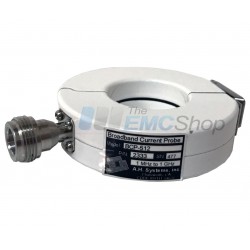
AH Systems BCP-512 Probe to Measure Conducted RF Currents, 1 MHz - 1 GHz
-
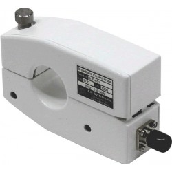
AH Systems BCP-610 High Power RF Current Probe, 20 Hz - 20 MHz
-
Rent AH Systems BCP-611 10 KHz – 150 MHz Broadband Current Probe
-
Haefely IP4A Capacitive Coupling Clamp for IEC 61000-4-4
-
Com-Power CLA-050 10mm Absorbing Clamp
-
Rent Amplifier Research 2000LM20, 1 - 200 MHz, 2 kW RF Power Amp
-
Monthly Rental: E&I / ENI 2200L 200W RF Power Amplifier 10 kHz - 12 MHz
-
EMCO (ETS-Lindgren) 3810-2 LISN, NEMA, 9 kHz - 30 MHz, 10 Amps
-
Rent Haefely PSURGE 4010 Surge Generator for IEC 61000-4-5 Testing
-
Rent Haefely PIM 100 Combination Wave Impulse Module for IEC 61000-4-5 and ANSI C62.41
-
Rent Haefely PSURGE 8000/PIM 150 Ring Wave & Damp Oscillating Wave Impulse System
-
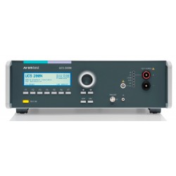
Rent EM Test UCS 200N50 ISO 7637 EMC Generator for Automotive Waveforms 1,2a, 3a, 3b
-
Haefely PEFT 8010 High Voltage EFT/Burst Generator, 7.3kV
-
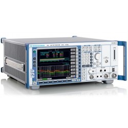
Rent Rohde & Schwarz ESU40 EMI Test Receiver for CISPR and MIL-STD Testing
-
Rent Haefely ONYX 30 ESD Simulator Gun
-
Monthly Rental Teseq (Schaffner) CDN T002 Coupling Network for Unshielded Balanced Pairs
-
Rent Haefely ECOMPACT4 Surge & EFT/Burst Simulator for IEC 61000-4-4 and 4-5
-
Rent Keytek ECAT Ring Wave Simulator for ANSI/IEEE C62.4 and UL 864
-
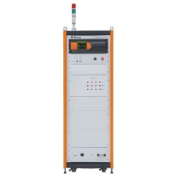
3ctest SG 5010H 10kV Surge Simulator for IEC 61000-4-5, GB/T, ITU-T K21/K44
-
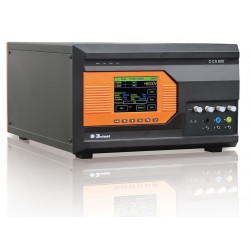
3ctest CCS 600 Conducted Immunity Test System (Surge, EFT)
-
3ctest LSS 160SS Single Stroke Test System for DO-160 Section 22 Pulses 1, 4, 5A, 5B
-
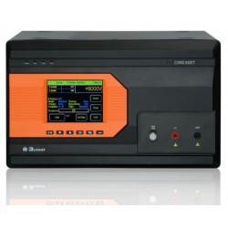
3ctest CWS 600T 10/700us Telecom Wave Surge Simulator for IEC 61000-4-5
-
Rent 3ctest CWS 600 6kV Surge Simulator for IEC 61000-4-5
-
3ctest CWS 600CT Combination Wave & Telecom Surge Simulator, 1.2/50us 8/20us 10/700us 5/320us
-
AH Systems CPF-631 Current Probe Calibration Fixture
-
Rent EM Test ESD NX30 Electrostatic Discharge Simulator Gun System for up to 30kV Testing
-
AH Systems BCP-614 Probe to Measure Conducted RF Currents, 10 KHz - 300 MHz
-
Com-Power Turn Key Conducted Immunity Test System up to 250 MHz
-
Com-Power ISN-T8 Impedance Stabilization Network 150 kHz to 30 MHz
-
Rent 3ctest TIS 700 Automotive Transient Simulator ISO 7637 Pulse 1,2a,3a/b