
Cart 0 Product Products (empty)
No products
TBD Shipping
$0.00 + Shipping Total
Product successfully added to your shopping cart
Quantity
Total
There are 0 items in your cart. There is 1 item in your cart.
Total products
Total shipping TBD
Total + Shipping
Voltage Dips and Interruptions Testers
- EMC Test Equipment
- Transient Generators
- RF Power Amplifiers
- DC - 300 kHz RF Amplifiers
- 10 kHz - 250 MHz RF Amplifiers
- 10 kHz - 400 MHz RF Amplifiers
- 10 kHz - 1 GHz RF Amplifiers
- 80 MHz - 1 GHz RF Amplifiers
- 1 GHz - 2 GHz RF Amplifiers
- 700 MHz - 4.2 GHz RF Amplifiers
- 1 GHz - 6 GHz RF Amplifiers
- 2 GHz - 8 GHz RF Amplifiers
- 6 GHz - 18 GHz RF Amplifiers
- 18 GHz - 40 GHz RF Amplifiers
- Pulse Amplifiers
- RF Field Strength Probes & Meters
- RF Conducted Immunity
- EMC Receivers/EMI Analyzers
- EMC Antennas
- Coupling Decoupling Networks (CDN's)
- Line Impedance Stabilization Networks (LISN's)
- RF Test Equipment
- EMC Probes
- EMC Measurement & Equipment Software
- Power Supplies
- Electrical Safety Analyzers
- High Precision Laboratory Power Analyzers & Meters
- Anechoic Chambers
- Over-the-Air (OTA) Test Chambers
- EMI RF Shielded Tent Enclosures
- RF Shielded Rooms
- EMC Absorber
- Positioning Equipment
- EMC/EMI Test Setup
- GTEM Cells / TEM Cells
- Reverberation Chambers
- Used RF Anechoic Chambers
- EMC Chamber Filters
- EMC Chamber Shielding Gaskets
- RF Shielded Doors
- Anechoic Chamber Accessories
- Fully Anechoic (FAR) Test Chambers
- Manufacturers
- 3ctest
- AE Techron
- AH Systems
- Amplifier Research
- Boonton
- Com-Power
- Diamond Engineering
- EM Test (Ametek CTS)
- EMC Partner
- EMC Test Design
- Empower High Power RF Amplifiers
- ETS-lindgren
- Log Periodic Dipole Array Antenna
- Near Field Probe Sets
- Double Ridge Horn Antennas
- Biconical Antennas
- Quad Ridge Horn Antennas
- Electric Field Probes
- GTEM's
- Positioners & Tripods
- Loop Antennas
- Biconilog Antennas
- LISN's (Line Impedance Stabilization Network)
- Shielded Enclosures/Rooms
- Monopole Antennas
- Field Generating Antennas
- Fischer Custom Communications
- Haefely Hipotronics
- Haefely EFT/Burst Immunity Test Systems
- Haefely Surge Combination Wave Test Systems
- Haefely Surge Damped Oscillating Wave Test Systems
- Haefely Electrostatic Discharge Test Systems (ESD)
- Haefely Surge Ring Wave Test Systems
- Haefely Surge Telecom Wave Test Systems
- Haefely Magnetic Field Test Systems
- Haefely CDN's (Coupling/Decoupling Networks)
- IFI Amplifiers
- Keysight (Agilent)
- MVG - Microwave Vision Group
- PMM / Narda
- Rohde & Schwarz RF Test Equipment
- Rohde & Schwarz Broadband RF Amplifiers
- Rohde & Schwarz Spectrum Analyzers
- Rohde & Schwarz Compliant EMI Test Receivers
- Rohde & Schwarz Isotropic RF Probes
- Rohde & Schwarz RF Signal Generators
- Rohde & Schwarz RF Switches
- Rohde & Schwarz Oscilloscopes
- Rohde & Schwarz RF Power Meters
- Rohde & Schwarz RF Power Sensors
- Schloder
- Schwarzbeck Mess-Elektronik
- Schwarzbeck Antennas
- Schwarzbeck Automotive Antennas
- Schwarzbeck Broadband Horn Antennas
- Schwarzbeck Biconical Antennas
- Schwarzbeck Logarithmic Periodic Broadband Antennas
- Schwarzbeck Stacked Log-Periodic Broadband Antennas
- Schwarzbeck Biconic Log-Periodic Antennas
- Schwarzbeck Dipole Antennas
- Schwarzbeck Rod Antennas
- Schwarbeck Antenna Baluns / Holders
- Schwarzbeck LISN Line Impedance Stabilisation Networks
- Schwarbeck Decoupling & Absorbing Clamps
- Schwarzbeck Field Probes
- Schwarzbeck Helmholtz Coils
- Schwarzbeck Antenna Masts
- Schwarzbeck Coupling/Decoupling Networks
- Schwarzbeck Antennas
- Solar Electronics
- Teseq (Schaffner)
- Teseq Automotive Transient Generators
- Teseq RF Test Equipment
- Teseq EFT/Burst Generators
- Teseq RF Immunity Generators
- Teseq ESD Guns
- Teseq Surge Generators
- Teseq Harmonics & Flicker Solutions
- Teseq Dips, Interrupts & Variations Equipment
- Teseq Ring Wave Generators
- Teseq Oscillatory Waves Generators
- Teseq Absorbing Clamps / Ferrite Tube
- Teseq EMC Antennas
- Teseq Current Probes
- Teseq Coupling Networks
- Thermo Keytek
- Vicreate
- Compliance Standards
- International (IEC/EN)
- EN/IEC 61000-3-2
- EN/IEC 61000-3-3
- IEC 61000-3-11
- IEC / EN 610000-3-12
- EN/IEC 61000-4-2
- EN/IEC 61000-4-3
- EN/IEC 61000-4-4
- EN/IEC 61000-4-5
- EN/IEC 61000-4-6
- EN/IEC 61000-4-7
- EN/IEC 61000-4-8
- EN/IEC 61000-4-9
- EN/IEC 61000-4-10
- EN/IEC 61000-4-11
- EN/IEC 61000-4-12
- EN/IEC 61000-4-16
- EN/IEC 61000-4-18
- EN/IEC 61000-4-19
- EN/IEC 61000-4-20
- EN/IEC 61000-4-21
- EN/IEC 61000-4-29
- EN/IEC 61000-4-31
- IEC 61000-4-39
- EN/IEC 62132
- SEMI F47 Voltage Sag Immunity
- Product Standards
- Military & Aerospace Standards
- Automotive EMC Standards
- CISPR Standards
- Telecom Testing
- ANSI/IEEE Standards
- FCC Part 15
- FCC Part 30
- International (IEC/EN)
- Application/Test Type
- Radiated Immunity
- Bulk Current Injection Testing
- RF Emissions Testing
- Conducted Immunity
- Conducted Emissions
- Antenna Pattern Measurement
- CE Mark Testing
- Intentional Radiator Testing
- Pulsed HIRF Radar
- Over-the-Air (OTA) Testing
- 5G Test Solutions
- Automotive EMC
- SAR Measurement Equipment
- Radiated Emissions
- Battery Simulator Test Equipment
- Services
- Clearance
Viewed products
-

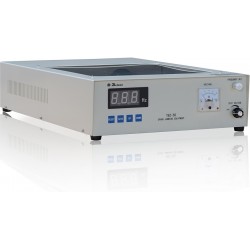
Schloder VIS 1700...
280 V AC max. 360 V DC max....
-

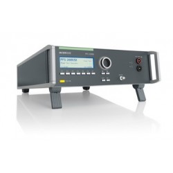
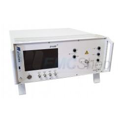
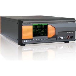
Haefely AXOS8 7kv...
Automatic 10/700us Telecom Wave...
 View larger
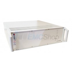
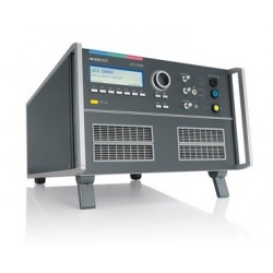
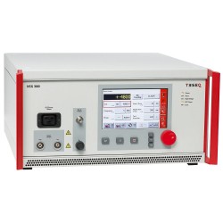
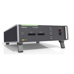
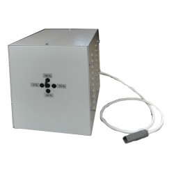
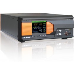
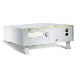
Schloder VIS 1700 Voltage Interruption Simulator
New
- 280 V AC max.
- 360 V DC max.
- AC-Test: IEC / EN 61000-4-11
- DC-Test: IEC / EN 61000-4-29
- Inrush Current Measurement at any Phase Position 0° - 360 °
- Automatic AC + DC Ramp Function
The EMC Shop
PDF Downloads
Specifications
| Supply Voltage | 230V / 50 Hz, 80VA, |
| Mains & EUT Connections | 4mm banana line |
| Dips, Interrupts & Variations Conforms to IEC/EN 61000-4-11, IEC/EN 61000-4-29 | |
| Parameter | Value |
| Peak inrush current capability | 16 Amps |
| Test duration | 0.1sec - 9990sec, furthermore single event and continuous operation |
| Repetition time | Asynchronous 5,0ms -9990ms Synchronous 20ms - 9980ms |
| Input | 230V / 50 Hz, 80VA |
| Phase synchronization | at any phase position 0° - 360 ° |
| Output Current | AC max. 280 V, DC max. 3 6 0 V |
| Test Voltage | AC max. 280 V ,DC max. 3 6 0 V |
| Coupling | BNC |
| Trigger | BNC |
| Communication | BNC outputs (on rear) for voltage, current and scope triggering |
| General Data Technical Details | |
| Parameter | Value |
| Dimensions | 19″ housing, 3 HE |
| Weight | 13 Kg |
Test Equipment Description
Schloder VIS 1700 Voltage Interruption Simulator
The clearly adjustable simulator VIS 1700 can simulate the voltage dips and voltage variations that can be found on supply nets (AC and DC). Different modes of operation are possible:
Performance feature
- Short interruptions 100%: - AC and DC
The supply network of the EUT can be interrupted in any phase position for a defined time
- Voltage dips - phase relation
Voltage drops on 40%, 70% or 80% of rated voltage can also be simulated at a given phase angle and time X. This test requires a second power source that meets a step transformer of sufficient capacity - see option VIS 740.
- Voltage fluctuation - AC and DC
Supply voltage fluctuations are typically carried out in a "ramp function". The VIS 1700 realized this in both AC and DC. The "fall time", the test time and "recovery time" can be set individually. Connecting a second voltage source is not required. - Inrush current measurement
This special function allows a quick and easy way to determine the inrush current of the device under test (DUT) with respect to phase. It should be set only two values - phase angle and break time. After pressing the start button the voltage of the DUT is interrupted and switched on at the set phase angle again. The peak value of the inrush current is shown in the display, but can also be shown via an oscillograph.
Associated EMC Test Equipment
30 other products in the same category:
-
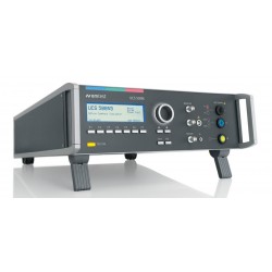
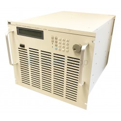
EM Test UCS500N7 Multifunctional Transient Immunity Simulator
-
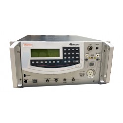
Rent Thermo Keytek EMCPro Plus EMC Test System
-
EM Test VDS 200Q Four Quadrant Battery Supply Simulator and DC Voltage Source
-
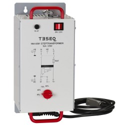
Teseq INA 6501 Manual Step Transformer for AC Dips & Interruptions
-
Teseq NSG 3040-IEC Test System for Surge Combination Wave, EFT/Burst, Dips Interrupts & Variations w/ 16 A CDN
-
3ctest Voltage Dips & Power Frequency Module (VMT, VVT, MFT)
-
Keytek (Thermo Fisher) EMCPro for Surge, Burst, & PQF
-
Keytek (Thermo Fisher) CE Master for EFT, Surge, PQF
-
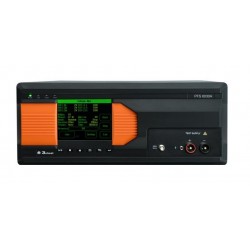
3ctest PFS 6050A Power Failure Simulator for Automotive Dips & Drops (micro interruption) up to 60V DC
-
EM Test PFM 200N100.1 Automotive Power Fail Simulator for Power Supply and Data Lines
-
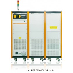
EM Test PFS 503N32 Power Fail Simulator, 3-phase 3x480V AC (p-p) max. 32A
-
3ctest PFS 2216SVD Single Phase Power Fail Simulator w/ Two Semiconductor Switches for High Current Protection
-
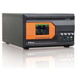
3ctest CCS 600 Conducted Immunity Test System (Surge, EFT)
-
Rent Haefely AXOS5 Transient Immunity Test System with Surge and EFT/Burst
-
Rent CE Marking Conducted Immunity Transient Test System - Keytek EMCPro Plus w/ Keytek Minizap MZ-15
-
Schloder VIS 740 Step Transformer for Voltage Drops, IEC/EN 61000-4-11
-

Rent Chroma 61704 3-Phase AC Power Source for MIL-STD-704 and RTCA DO-160 Testing
-
Chroma 61704 3-Phase AC Power Source for MIL-STD-704 and RTCA DO-160 Testing
-
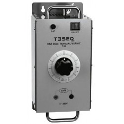
Rental Teseq VAR 6503 Manual Variable Transformer For NSG 3040 and NSG 3060/CDN 3061
-
3ctest PFS Series Single Three-Phase Power Fail
-
3ctest TIS 700x Compact Transient Immunity Simulator TIS
-
EM Test PFS 500 Power Fail Simulator for EN/IEC 61000-4-11
-
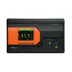
3ctest PFS 6075A Automotive Power Failure Simulator
-

3ctest PFS 60100A Automotive Power Failure Simulator
-
3ctest VTE-743T1 Automotive Voltage Transient Disturbance Tester
-
3ctest TBZ-50 Automotive Spark Immunity Simulator
-

3ctest VSG 1200/2000 VSG Series Voltage Impulse Simulator
-
3ctest SG 384G HV Pulsed Simulator
-
3ctest VSG256 VSG Series Voltage Impulse Simulator
-
3ctest VSS 1000/2000 VSS Series Voltage Impulse Simulator