
No products
Product successfully added to your shopping cart
There are 0 items in your cart. There is 1 item in your cart.
EM Test Transient Generators
- EMC Test Equipment
- Transient Generators
- RF Power Amplifiers
- DC - 300 kHz RF Amplifiers
- 10 kHz - 250 MHz RF Amplifiers
- 10 kHz - 400 MHz RF Amplifiers
- 10 kHz - 1 GHz RF Amplifiers
- 80 MHz - 1 GHz RF Amplifiers
- 1 GHz - 2 GHz RF Amplifiers
- 700 MHz - 4.2 GHz RF Amplifiers
- 1 GHz - 6 GHz RF Amplifiers
- 2 GHz - 8 GHz RF Amplifiers
- 6 GHz - 18 GHz RF Amplifiers
- 18 GHz - 40 GHz RF Amplifiers
- Pulse Amplifiers
- RF Field Strength Probes & Meters
- RF Conducted Immunity
- EMC Receivers/EMI Analyzers
- EMC Antennas
- Coupling Decoupling Networks (CDN's)
- Line Impedance Stabilization Networks (LISN's)
- RF Test Equipment
- EMC Probes
- EMC Measurement & Equipment Software
- Power Supplies
- Electrical Safety Analyzers
- High Precision Laboratory Power Analyzers & Meters
- Anechoic Chambers
- Over-the-Air (OTA) Test Chambers
- EMI RF Shielded Tent Enclosures
- RF Shielded Rooms
- EMC Absorber
- Positioning Equipment
- EMC/EMI Test Setup
- GTEM Cells / TEM Cells
- Reverberation Chambers
- Used RF Anechoic Chambers
- EMC Chamber Filters
- EMC Chamber Shielding Gaskets
- RF Shielded Doors
- Anechoic Chamber Accessories
- Fully Anechoic (FAR) Test Chambers
- Manufacturers
- 3ctest
- AE Techron
- AH Systems
- Amplifier Research
- Boonton
- Com-Power
- Diamond Engineering
- EM Test (Ametek CTS)
- EMC Partner
- EMC Test Design
- Empower High Power RF Amplifiers
- ETS-lindgren
- Log Periodic Dipole Array Antenna
- Near Field Probe Sets
- Double Ridge Horn Antennas
- Biconical Antennas
- Quad Ridge Horn Antennas
- Electric Field Probes
- GTEM's
- Positioners & Tripods
- Loop Antennas
- Biconilog Antennas
- LISN's (Line Impedance Stabilization Network)
- Shielded Enclosures/Rooms
- Monopole Antennas
- Field Generating Antennas
- Fischer Custom Communications
- Haefely Hipotronics
- Haefely EFT/Burst Immunity Test Systems
- Haefely Surge Combination Wave Test Systems
- Haefely Surge Damped Oscillating Wave Test Systems
- Haefely Electrostatic Discharge Test Systems (ESD)
- Haefely Surge Ring Wave Test Systems
- Haefely Surge Telecom Wave Test Systems
- Haefely Magnetic Field Test Systems
- Haefely CDN's (Coupling/Decoupling Networks)
- IFI Amplifiers
- Keysight (Agilent)
- MVG - Microwave Vision Group
- PMM / Narda
- Rohde & Schwarz RF Test Equipment
- Rohde & Schwarz Broadband RF Amplifiers
- Rohde & Schwarz Spectrum Analyzers
- Rohde & Schwarz Compliant EMI Test Receivers
- Rohde & Schwarz Isotropic RF Probes
- Rohde & Schwarz RF Signal Generators
- Rohde & Schwarz RF Switches
- Rohde & Schwarz Oscilloscopes
- Rohde & Schwarz RF Power Meters
- Rohde & Schwarz RF Power Sensors
- Schloder
- Schwarzbeck Mess-Elektronik
- Schwarzbeck Antennas
- Schwarzbeck Automotive Antennas
- Schwarzbeck Broadband Horn Antennas
- Schwarzbeck Biconical Antennas
- Schwarzbeck Logarithmic Periodic Broadband Antennas
- Schwarzbeck Stacked Log-Periodic Broadband Antennas
- Schwarzbeck Biconic Log-Periodic Antennas
- Schwarzbeck Dipole Antennas
- Schwarzbeck Rod Antennas
- Schwarbeck Antenna Baluns / Holders
- Schwarzbeck LISN Line Impedance Stabilisation Networks
- Schwarbeck Decoupling & Absorbing Clamps
- Schwarzbeck Field Probes
- Schwarzbeck Helmholtz Coils
- Schwarzbeck Antenna Masts
- Schwarzbeck Coupling/Decoupling Networks
- Schwarzbeck Antennas
- Solar Electronics
- Teseq (Schaffner)
- Teseq Automotive Transient Generators
- Teseq RF Test Equipment
- Teseq EFT/Burst Generators
- Teseq RF Immunity Generators
- Teseq ESD Guns
- Teseq Surge Generators
- Teseq Harmonics & Flicker Solutions
- Teseq Dips, Interrupts & Variations Equipment
- Teseq Ring Wave Generators
- Teseq Oscillatory Waves Generators
- Teseq Absorbing Clamps / Ferrite Tube
- Teseq EMC Antennas
- Teseq Current Probes
- Teseq Coupling Networks
- Thermo Keytek
- Vicreate
- Compliance Standards
- International (IEC/EN)
- EN/IEC 61000-3-2
- EN/IEC 61000-3-3
- IEC 61000-3-11
- IEC / EN 610000-3-12
- EN/IEC 61000-4-2
- EN/IEC 61000-4-3
- EN/IEC 61000-4-4
- EN/IEC 61000-4-5
- EN/IEC 61000-4-6
- EN/IEC 61000-4-7
- EN/IEC 61000-4-8
- EN/IEC 61000-4-9
- EN/IEC 61000-4-10
- EN/IEC 61000-4-11
- EN/IEC 61000-4-12
- EN/IEC 61000-4-16
- EN/IEC 61000-4-18
- EN/IEC 61000-4-19
- EN/IEC 61000-4-20
- EN/IEC 61000-4-21
- EN/IEC 61000-4-29
- EN/IEC 61000-4-31
- IEC 61000-4-39
- EN/IEC 62132
- SEMI F47 Voltage Sag Immunity
- Product Standards
- Military & Aerospace Standards
- Automotive EMC Standards
- CISPR Standards
- Telecom Testing
- ANSI/IEEE Standards
- FCC Part 15
- FCC Part 30
- International (IEC/EN)
- Application/Test Type
- Radiated Immunity
- Bulk Current Injection Testing
- RF Emissions Testing
- Conducted Immunity
- Conducted Emissions
- Antenna Pattern Measurement
- CE Mark Testing
- Intentional Radiator Testing
- Pulsed HIRF Radar
- Over-the-Air (OTA) Testing
- 5G Test Solutions
- Automotive EMC
- SAR Measurement Equipment
- Radiated Emissions
- Battery Simulator Test Equipment
- Services
- Clearance
Viewed products
-

EM Test TSS 500M10...
Standalone tester for 10 / 700us...
 View larger
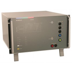
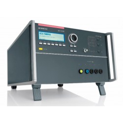
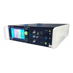
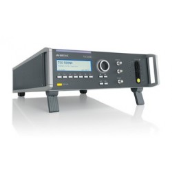
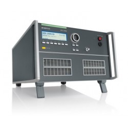
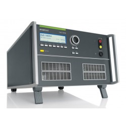
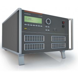
EM Test TSS 500M10 Telecom Surge Generator
Refurbished
- Standalone tester for 10 / 700us pulse according to IEC 61000-4-5
- Test voltage up to 10kV
- Compliant with ITU-T standard for enhanced test level
- Complies with FCC part 68 (Surge B pulses)
- Integrated CDNs for 2-wire and 4-wire applications
- Manual operation
- Standard test procedures
- RS232 and GPIB interfaces
PDF Downloads
Test Equipment Description
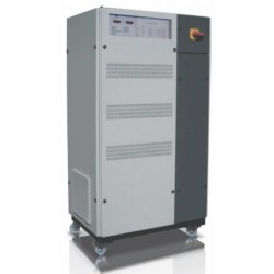
EM Test TSS 500M10 Telecom Surge Generator for Test Pulse 10 / 700us
Telecommunication networks are exposed to lightning. As a result, external telecommunication equipment needs appropriate protection to be immune to lightning shock waves. Surge Telecom TSS 500 series simulators are used to test the immunity of telecommunications equipment.
The TSS 500M10 is used to perform tests in accordance with IEC 61000-4-5 and related standards in accordance with the requirements of ITU-T and FCC 97-270 (part 68) for the Surge B pulse.
Advantages
TSS 500M10 - pulse generation 10 / 700us and coupling network in a single unit
The TSS 500M10 is a compact tester for generating Surge Telecom 10 / 700us and 9 / 720us pulses, as well as the Surge 1.2 / 50us voltage pulse. The TSS 500M10 is not only the pulse generator, but it also integrates coupling networks for 2 and 4-wire test applications. The outputs can be directly connected to the Telecom ports of the sample under test. For Telecom test lines, EM TEST offers suitable coupling networks for 4 and 8-wire lines. Preprogrammed standard test parameters allow for greater convenience of use. Nevertheless, the TSS 500M10 offers the Quick Start test procedure, in which the parameters can be changed on-line during the test to assess the susceptibility level of an individual DUT.
Operation
Easy to use Zoom
The Front Front Function Keys allow the user to program these test procedures quickly and accurately. The slider allows quick control of all test parameters of the programmed procedure, and thus the test procedures are simplified so that each step is performed correctly.
| Specifications | |
| AS PER ITU AND ETS RECOMMENDATIONS | |
| Output Voltage Open Circuit (o.c.) | 500 V - 10,000 V ± 10% |
| Pulse 1.2/50 μs | |
| Pulse duration*)5 | 50 us ± 20% |
| Energy storage capacitor | 1 μF |
| Pulse 10/700 μs | |
| Rise time tr* | 6.5μs ± 30% |
| Pulse duration*) | 700 μs ± 20% |
| Energy storage capacitor | 20 μF |
| Polarity | Positive, negative or alternating |
| Counter select | 1 - 30,000 or endless |
| AS PER IEC 61000-4-5 | |
| Pulse 10/700μs | |
| Open circuit output voltage | 500V - 10,000V ±10% |
| Rise Time tr* | 6.5μs ± 30% |
| Pulse duration td* | 700μs ± 20% |
| Short Circuit Output Current | 12.5 - 250A for T1 to Com or T2 to Com |
| Rise Time tr* | 4μs ± 20% |
| Pulse duration td* | 300μs ± 20% |
| Energy Storage Capacitor | 20μF |
| Source Impedance | 40Ω (15Ω from generator and 25Ω at Tx) |
| Polarity | Positive, negative or alternating |
| Counter Select | 1-30,000 or endless |
| Coupling | |
| As per ITUA | For 2 wire T1 and T2 with 25Ω each For 4 wire T1, T2, T3, T4 with 25Ω each |
| As per FCC part 68 | For 2 wire T1 and T2 with 25Ω each |
| As per IEC 61000-4-5 | External networks are required (options) |
| Trigger | |
| Automatic | Automatic pulse release |
| Manual | Single pulse release |
| External | External pulse release |
| CRO Trigger | 5V trigger signal for oscilloscope |
| Test Routines | |
| Quick Start | Immediate Start, easy to use and fast |
| User Test Routines | Change Polarity after n pulses Change voltage after n pulses by △Voltage |
| Service | Service, setup, self test |
| Interface | |
| Serial Interface | RS 232, baud rate 1200 - 19,200 |
| Parallel Interface | IEEE 488, address 1-30 |
| Safety | |
| Safety circuit | Control input (24Vdc) |
| Warning lamp | Floating output contact |
| General dataDimensions, weight | 19" / 6HU, approx. 35kg |
| Supply voltage | 115/230V + 10/-15% |
| Fuses | 2 x T 2AT (230V) or 2 x T4AT (115V) |
| Options | |
| CNV 504S1 | 4 telecom lines as per fig. 12 IEC 61000-4-5 |
| CNV 508S1 | 8 telecom lines as per fig. 12 IEC 61000-4-5 |
| CNV 504S5 | Coupling Network Providing 4x100ohm and 2x25ohm |
| Model Configuration | |
| T1-M10* | 0.5/700μs up to 10kV |
| T2-M10* | 100/700μs up to 10kV *to replace one of the standard pulses |
| *definition of waveform parameter as per IEC 469-1. Acc. to IEC 61000-4-5 this is considered to be equal to the waveform parameter definition as per IEC 60-1 fot he 1.2/50μs pulse and CCITT for the 10/700μs pulse. | |
Associated EMC Test Equipment

30 other products in the same category:
-

EM Test Automotive Transient Emission Set for ISO 7637-2
-
EM Test OCS 500N6F Simulator for Fast/Slow Damped Oscillatory Waves and Ringwave
-
EM Test OCS 500N6 Compact Tester for Ringwave and Damped Oscillatory Waves
-
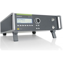
EM Test TSS 500N10 Telecom Surge Generator ITU-T for Enhanced Level Testing up to 10 kV
-
EM Test AMP 200N Low Frequency Signal Source DC (0Hz) to 250kHz
-
Rent EM Test Dito 16.5 kV ESD Simulator for IEC/EN 61000-4-2
-
EM Test Dito ESD Simulator up to 16.5 kV for IEC/EN 61000-4-2
-
EM Test ESD NX30 Electrostatic Discharge Simulator Gun System for up to 30kV Testing
-
EM Test PFS 503N32 Power Fail Simulator, 3-phase 3x480V AC (p-p) max. 32A
-
EM Test NX5 Compact EMC Generator for EFT/Burst, Surge & Power Fail up to 5.5 kV
-
EM Test TSS 500N4 Telecom Surge Generator as per ITU / FCC up to 4 kV
-
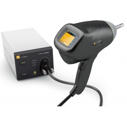
Rent EM Test ESD NX30 Electrostatic Discharge Simulator Gun System for up to 30kV Testing
-
Used EM Test UCS 500M4 Transient Simulator w/ Burst/EFT
-
Em Test CWS 500N1.4 RF Conducted Immunity Test System for IEC 61000-4-6
-
Rent EM Test VDS 200N10 Automotive Battery Source and Voltage Drop Simulator, 60 V/10 A
-
EM Test DPA 500N Power Analyzer for Harmonics & Flicker
-
EM Test UCS500N7 Multifunctional Transient Immunity Simulator
-
EM Test UCS 500N5 Multifunctional Generator for EFT/Burst, Surge & Power Fail up to 5.5kV
-
EM Test ACS 503N30 AC Voltage Source for Harmonics & Flicker Compliance Testing
-
Rent EM Test UCS 200N50 ISO 7637 EMC Generator for Automotive Waveforms 1,2a, 3a, 3b
-
EM Test EFT 500N5.8 Burst Generator up to 4.8kV, w/ Built in 3-Phase Coupler, IEC 61000-4-4
-
Rent EM Test DPA 503N 3 Phase Harmonics & Flicker Power Analyzer
-
EM Test CWS 500N4 Common-Mode Disturbance Simulator for IEC 61000-4-16 & IEC 61000-4-19
-
EM Test UCS 200N50 Automotive Transient Simulator for Pulses 1, 2, 3A/3B
-
Rent EM Test TSS 500M2F Telecom Surge Simulator for FCC Part 68
-
EM Test VCS 500N10 Combination Wave Simulator for IEC/EN 61000-4-5 up to 10kV/5kA
-
EM Test LD 200N Automotive Load Dump Generator for ISO 7637 Pulses 5 and 7
-
Rent EM Test Compact NX5 B-1-300-16 EFT/Burst Generator
-

EM Test Compact NX5 B-1-300-16 5.5kV EFT/Burst Generator
-
Monthly Rental EM Test CWS 500N Continuous Wave Simulator for IEC 61000-4-6